TL;DR - I used an LED matrix to create a custom art piece that visualizes popular computer algorithms.
A lot of programming can get abstract, especially when we start work with datasets, statistical tools, and AI systems. In this post we're going to take things back to the basics by bridging the gap between programming and real-world physical systems via a little art project I've been working on in the background.
Hardware
The easiest way to bridge this gap between programming and real-world systems is with the use of microelectronics. Microelectronics are small motors, sensors, and other components that can be programmed to move, collect data, or perform some other physical function. One of the most fun, intuitive, and visually striking microelectronics are Light Emitting Diodes (LEDs). The main idea behind an LED is simple, you pass an electrical current through a component called a diode and it produces light.

LED Diagram Source: https://byjus.com/physics/light-emitting-diode/
One LED on is pretty basic but they get more interesting when we start chaining them together. While this can be organized in one long individual LED strip I think it's cooler / more stylized to use a compact matrix of LEDs. I purchased this 32x8 individually addressable WS2812B LED Matrix which has 3 inputs - power, ground, and signal. I didn't want to leave my laptop running all day just to support this art project so I dedicated a spare Raspberry pi 4B to it. If you're looking for even cheaper / more budget-friendly options you can also go with the Raspberry Pi Zero 2w or Raspberry Pi Pico. These Raspberry pi devices are inexpensive and energy efficient yet still pack enough compute to handle more complex programming logic for our LED matrix. The wiring configuration for this setup is quite simple:

Circuit Diagram made with https://app.cirkitdesigner.com/
Notably we use GPIO pin 18 to drive the signal since it supports Pulse Width Modulation, a feature which can rapidly switch the LEDs on and off enabling dimming on LEDs. One last component we can add to this hardware setup is what's called a diffuser. A diffuser is a thin material that is placed over the LED to help diffuse the concentrated LED light across a wider surface area. I 3D printed a diffuser (and a nice case) using the following BiFROST LED Case files. The end result goes from something like this:
to this:
One other thing we may want to add to this setup is a way to extend the range that we send the signal. The small jumper cables are nice for prototyping, but eventually we'll need additional range if we want to place this pixel matrix further than a foot away from the raspberry pi itself. Interestingly both signal and power can be provided by ethernet cables! This can help us place our pixel matrix wherever we want! Here we can see I had my pixel matrix set up near my desk:

We'll talk more about what we'll display in just a moment. For now we can see the pixel matrix in its current configuration, finding its own little place in my homelab in Las Vegas:

All of these materials are also consolidated at the end of this blog post for your convenience.
Software
Getting Started
Great! Now we can take a look at the programming side of this project. The low-level logic is handled efficiently by a library called rpi_ws281x. Let's start by turning on pixel 0 in our pixel matrix:
from rpi_ws281x import Adafruit_NeoPixel, Color
# Assistance from NeoPixel library strandtest example by Tony DiCola (tony@tonydicola.com)
# LED strip configuration:
LED_COUNT      = 256      # Number of LED pixels (32 x 8 = 256).
LED_PIN        = 18       # GPIO pin connected to the pixels (18 uses PWM!).
LED_FREQ_HZ    = 800_000  # LED signal frequency in hertz (usually 800khz)
LED_DMA        = 10       # DMA channel to use for generating signal (try 10)
LED_BRIGHTNESS = 255      # Set to 0 for darkest and 255 for brightest
LED_INVERT     = False    # True to invert the signal (when using NPN transistor level shift)
LED_CHANNEL    = 0        # set to '1' for GPIOs 13, 19, 41, 45 or 53
# Create NeoPixel object with the above configuration.
strip = Adafruit_NeoPixel(LED_COUNT, LED_PIN, LED_FREQ_HZ,
                          LED_DMA, LED_INVERT, LED_BRIGHTNESS,
                          LED_CHANNEL)

# Intialize the library (must be called once before other functions).
strip.begin()
# Clear the LED strip before executing the new code
for i in range(strip.numPixels()): strip.setPixelColor(i, Color(0,0,0))
# Set the first pixel to high brightness
strip.setPixelColor(0, Color(255,255,255))
strip.show()
When we run the script, we can see that the very first pixel (pixel 0) is activated at full brightness!
Source: 0_light_up_pixel.py
We can also adjust the brightness and color of the pixel if we'd like using the following code:
from rpi_ws281x import Adafruit_NeoPixel, Color
import argparse
# Parse the CLI for arguments about our pixel
parser = argparse.ArgumentParser(
    prog="PixelPosition",
    description="Learn about the pixel matrix and alter individual pixel states",
)
parser.add_argument("-n", "--pixelnum", type=int, help="The pixel number to activate.", default=0)
parser.add_argument("-br", "--brightness", type=int, help="The brightness of the display, 0 is darkest and 255 is brightest.", default=25)
parser.add_argument("-rgb", type=int, help="The r, g, and b value of the activated pixel.", nargs=3, default=[255,255,255])
args = parser.parse_args()
# Assistance from NeoPixel library strandtest example by Tony DiCola (tony@tonydicola.com)
# LED strip configuration:
LED_COUNT      = 256      # Number of LED pixels (32 x 8 = 256).
LED_PIN        = 18       # GPIO pin connected to the pixels (18 uses PWM!).
LED_FREQ_HZ    = 800_000  # LED signal frequency in hertz (usually 800khz)
LED_DMA        = 10       # DMA channel to use for generating signal (try 10)
LED_BRIGHTNESS = args.brightness       # Set to 0 for darkest and 255 for brightest
LED_INVERT     = False    # True to invert the signal (when using NPN transistor level shift)
LED_CHANNEL    = 0        # set to '1' for GPIOs 13, 19, 41, 45 or 53
# Create NeoPixel object with the above configuration.
strip = Adafruit_NeoPixel(LED_COUNT, LED_PIN, LED_FREQ_HZ,
                          LED_DMA, LED_INVERT, LED_BRIGHTNESS,
                          LED_CHANNEL)

# Intialize the library (must be called once before other functions).
strip.begin()
# Clear the LED strip before executing the new code
for i in range(strip.numPixels()): strip.setPixelColor(i, Color(0,0,0))
# Set the first pixel to high brightness
pixel_num = args.pixelnum
r,g,b = args.rgb
strip.setPixelColor(pixel_num, Color(r,g,b))
strip.show()
This way we can pass in the pixel number, position, and brightness as command line arguments to easily control our pixel matrix:
sudo python 1_light_up_pixel.py -br 255 -rgb 255 0 0
Source: 1_vary_pixel_settings.py
We can also check a few different values to see the bounds of the pixel matrix, with corners at pixels 0, 7, 248, and 255:
Interestingly, as we increase the pixel number we can see that the LED number follows a snake pattern, going up and down the matrix. This follows the wiring pattern / setup of the LED grid itself.

Of course this is a little less intuitive than thinking of the board as a whole. Ideally we'd want a system where we can activate an LED based on their x and y position on this grid. Thankfully arrays (specifically matrices) are a well-understood data structure in programming. We can use numpy arrays to represent the board in our program and use some built-in functions to efficiently build out a board, transform its state, then find the corresponding x and y positions for any given pixel. The code for this looks like the following:
# Set up a matrix representing our pixel matrix
size = (32, 8)
state = np.zeros_like(size[0]*size[1], shape=size)

# Unpack the x and y position arguments and use them
# to set the state of our pixel
x, y = args.xy
state[x][y] = 1

# Apply the transformations to the original
transformed_state = transform_board_state(state)
pixelnum = int(np.where(transformed_state == 1)[0][0])
strip.setPixelColor(pixelnum, Color(r,g,b))
Where the transform_board_state function is defined below:
# Transform the board state matrix so that it directly
# maps onto the LED baord
def transform_board_state(state):
    # The board alternates indices, to make it match
    # the matrix we need to flip every other column
    # before outputting it to the board
    transformed_state = []
    for row, col in enumerate(state):
        if row % 2:
            col = np.flip(col)
        transformed_state.append(col)
    transformed_state = np.array(transformed_state)

    return np.flip(transformed_state).ravel()
This creates a 32 x 8 numpy array of 0s, sets the corresponding x y coordinate to a 1 to turn on the LED, then uses transform_board_state to flip every other column to account for the wiring pattern of our LED matrix. The result is a one-dimensional numpy array of all 256 pixels which helps us map the 32 x 8 matrix onto our pixel grid.
Rendering Images
Now that we can effectively map our numpy matrix to our LED strip, we can start to create all different kinds of visuals! I found the first and most intuitive to be a static image. I wanted to be able to make custom pixel art images in Aseprite (which could potentially be animated later on) then display them on my pixel matrix. This is essentially a two-step process:
- Load an image and extract the RGB value of each pixel, storing this data as a
32x8numpy array - Translate that
32x8numpy array of pixels onto the LED matrix.
I made the following tiny 32 x 8 banner to represent hearts, clubs, spades, and diamonds that I could display during poker nights:

To load this image in we can use the Pillow (PIL) python package:
# Load in our image and convert it to RGBA
img_to_load = "img/poker.png"
img_data = Image.open(img_to_load).convert("RGBA")
Additionally, we can create our own Pixel data structure to represent each individual pixel and its attributes:
# Define our Pixel data structure
class Pixel():
    def __init__(self, color=[0,0,0]):
        self.color = color
Now we can create a numpy array of data type Pixel to represent the pixel matrix. By loading in the image and its associated pixel colors at their x and y positions, we can translate the image (and its original colors) directly onto the board:

Source: 2_render_img.py
Nice! Now we've ported our tiny pixel art image onto our real-world pixel grid. Only issue is it can be kind of boring. If we want to add a little movement to our art piece we can periodically update the x position of the image to allow it to render as a banner that moves from right to left across the grid:
Source: 3_render_banner.py
Sending Messages
At this point we can easily transfer our static images to our pixel matrix. Another function we may want to add is the display of written messages. Thankfully there was a stack overflow post that tackled this exact problem. Their solution involves using python's PIL package to create an image of the text then deconstruct the pixels from that image back into a numpy array. Once the data is in the format of a 32 x 8 numpy array, we can use our previous functions to transfer that information onto the pixel matrix.
def display_message(msg_text, fontsize=8, color=[255,255,255]):
    font = ImageFont.truetype('/fonts/PixelOperator8.ttf', fontsize) #load the font
    size = np.array(font.getsize(msg_text))  #calc the size of text in pixels
    message = Image.new('1', tuple(size), 1)  #create a b/w image
    draw = ImageDraw.Draw(message)
    draw.text((0, 0), msg_text, font=font) #render the text to the bitmap
    message = message.convert("RGBA")
    # Split the image into individual bands
    r, g, b, a = message.split()
    # Invert the RGB channels
    r = ImageOps.invert(r)
    g = ImageOps.invert(g)
    b = ImageOps.invert(b)

    # Convert channels to NumPy arrays
    r_array = np.array(r)
    g_array = np.array(g)
    b_array = np.array(b)
    # Identify pixels where r, g, and b are 255
    mask = (r_array == 255) & (g_array == 255) & (b_array == 255)
    # Set g and b to 0 where the condition is met
    input_r, input_g, input_b = color
    r_array[mask] = input_r
    g_array[mask] = input_g
    b_array[mask] = input_b
    # Convert arrays back to Image objects
    r = Image.fromarray(r_array)
    g = Image.fromarray(g_array)
    b = Image.fromarray(b_array)

    # Merge the channels back together
    message = Image.merge("RGBA", (r, g, b, a))
    return message
This gives us our message in a numpy array format, but we can also be smarter about how we render the message. Since a message has a fixed length, we only need to light the pixels for as long as the message is moving across the screen (unlike an image or banner which may be rendered forever):
def render_message(msg_text, color=args.rgb, wait_ms=args.speed):
    img = display_message(msg_text=msg_text, color=color)
    # Transform the image to read correctly on the pixel grid
    img_array = np.rot90(np.array(img))
    # Add padding of zeros with shape 32x8x4 to the original array
    padding = ((33, 0), (0, 0), (0, 0))
    img_array = np.pad(img_array, padding, mode='constant', constant_values=0)
    params = {
        "current_pos":0,
        "x_offset": 0,
        "y_offset": 0
    }
    current_pos = -1
    while current_pos > -img_array.shape[0]:
        state = put_img_to_strip(img_array[current_pos:, :, :], **params)
        transformed_board = transform_board_state(state)
        for i, pixel in enumerate(transformed_board):
            r, g, b = pixel.color
            strip.setPixelColor(i, Color(r,g,b))
        time.sleep(wait_ms/1_000.0)
        strip.show()
        current_pos-=1
The result of sending a message is seen below:
Source: 4_send_message.py
And of course we can play around with different attributes of the message including color, brightness, and speed of the message by passing in different command line arguments:
sudo python3 4_send_message.py -m "DIMMiN says hello!" -rgb 230 35 75 -s 20
Visualizing Algorithms
Now that we have some of the basics out of the way, it's time to build some more custom visuals! There are plenty of LEDs / screens that can render images, but few that focus on visualizing computer science algorithms.
Conway's Game of Life
One of my favorite algorithms is Conway's Game of Life, a "zero-player game" that uses simple rules to build a complex system. Each pixel represents a cell which follows the logic outlined below:
- Any live cell with fewer than two live neighbors dies, as if by underpopulation.
- Any live cell with two or three live neighbors lives on to the next generation.
- Any live cell with more than three live neighbors dies, as if by overpopulation.
- Any dead cell with exactly three live neighbors becomes a live cell, as if by reproduction.
The code here starts to get more complicated, but the main idea is now we can use a Cell class to represent each pixel:
# A cell is the individual unit of Conway's
# Game of life
class Cell():

    def __init__(self):
        self.is_living = False
        self.map_color_to_int(0)
        # The number of consecutive steps that the cell was alive for
        self.steps_alive = 0
        self.num_living_neighbors = 0

    def __repr__(self):
        return f"{int(self.is_living)}"

    # Flip the state of the cell between states
    # of dead and alive
    def flip(self):
        self.is_living = not self.is_living

    # If the cell is alive return the cell's color
    # otherwise return no color for the LED board
    def get_color(self):
        if self.is_living:
            return self.color
        return (0,0,0)

    # Get the number of living neighbors associated with
    # this cell
    def get_num_living_neighbors(self):
        return self.num_living_neighbors

    # Map the color to an integer based on any number of things
    # (Total number of living cells,
    #  number of days this individual cell was alive,
    #  total number of neighbors this cell has,
    #  etc.)
    def map_color_to_int(self, integer_value, min_value=0, max_value=256):
        normalized_value = (integer_value - min_value) / (max_value - min_value)
        hue = 0.67 * normalized_value
        rgb = colorsys.hsv_to_rgb(hue,1,1)
        scaled_rgb = [int(val*255) for val in rgb]
        self.color = scaled_rgb
I've also decided to let the color of the cells represent the total number of cells on the board, so as they get closer to extinction the board gets redder. The result of simulating life over the entire LED matrix is demonstrated below:
Source: 5_conways_game_of_life.py
Depth First Search
Another neat algorithm to visualize is depth first search (DFS). DFS is designed to search as far throughout a tree structure (such as a network graph) as possible before it begins backtracking. We can create a maze and use DFS to help the red pixel explore long enough to reach the green pixel:
Source: 6_depth_first_search.py
The below example removes any artificial waiting I apply before rendering the next step:
Neural Networks
Finally, I wanted to show off one last visualization idea. Neural Networks consist of a collection of neurons which work together to make decisions based on an input of all different features. During inference (after the network has been trained and an input is given to the network), each neuron in the network has some numerical value associated with it. I wanted to train a basic neural network on the classic MNIST digit recognition classification problem, then represent each neuron's value during inference on my pixel matrix. Below we can see a model that consists of three densely-connected layers with a 32 x 16 x 10 architecture running inference on a collection of digits. Smaller values in the network are colored more red while larger values in the network are green. Cells that are completely red have been deactivated by the ReLU activation function. The pixels at the top are reserved for our network's classification prediction (i.e the pixel on the top at the far left represents a 0 digit classification while the pixel at the far right represents a 9). The more green the predicted pixel, the more confident the network is about its classification for that pixel. Inference across a collection of digits is seen below:
Source: neural_networks/neural_network.py (architecture models/network_0.pth or -n 0)
We can also extend this to different neural network architectures such as 32x16x16x8:
Source: neural_networks/neural_network.py (architecture models/network_1.pth or -n 1)
And just for fun, 32x28x22x18x12x10:
Source: neural_networks/neural_network.py (architecture models/network_3.pth or -n 3)
Future Work
Finally, there's the question of how to expand this system. If you want to power even more LED strips in series and make a massive neural network display, DFS maze solver, or game of life then you'll need a lot more power than a little Raspberry Pi can supply. Thankfully this can be supported (at your own risk of fire and increased electric bill) through the use of an additional 5V power supply that can provide power across your entire system. Then, some 14 gauge wire can be used to connect this power supply to the remaining pixel matrices. I never got too serious about adding many pixel grids together (though I did test that these components could supply adequate power to over a dozen matrices or 3k+ LEDs), but I have a feeling that a creative builder could put together a pretty cool project at scale.
A full parts list (including alternatives and potential upgrades) is provided below if you'd like to build your own:
- Individually Addressable LED Grid
- Raspberry Pi
- Raspberry Pi 4B (the one I used)
- RPi zero 2W (inexpensive alternative, still works great)
- RPi Pico W (extremely affordable small board)
- BiFROST LED case (3D printed diffuser and case)
- Ethernet Cable
- Ethernet to jumper cable adapter
- Upgrades / extensions
- 5V Power Supply
- 14 Gauge Wire (if you want to extend the signal even further, just be careful about heating of these wires when used with the additional power supply)
Additionally, all code used in this project is publicly available in this GitHub repo.
Conclusion
I've enjoyed building and playing around with this little setup. It's fun to get back to working with circuits and easily programmable microelectronics. As always I have some other ideas in mind for how I may want to integrate this with an existing project, but for now it is a fun way to send friends and family custom messages like:

Spending Way Too Much Time at Bars - My First Ultralearning Project
Sept. 4, 2022, 2:39 a.m.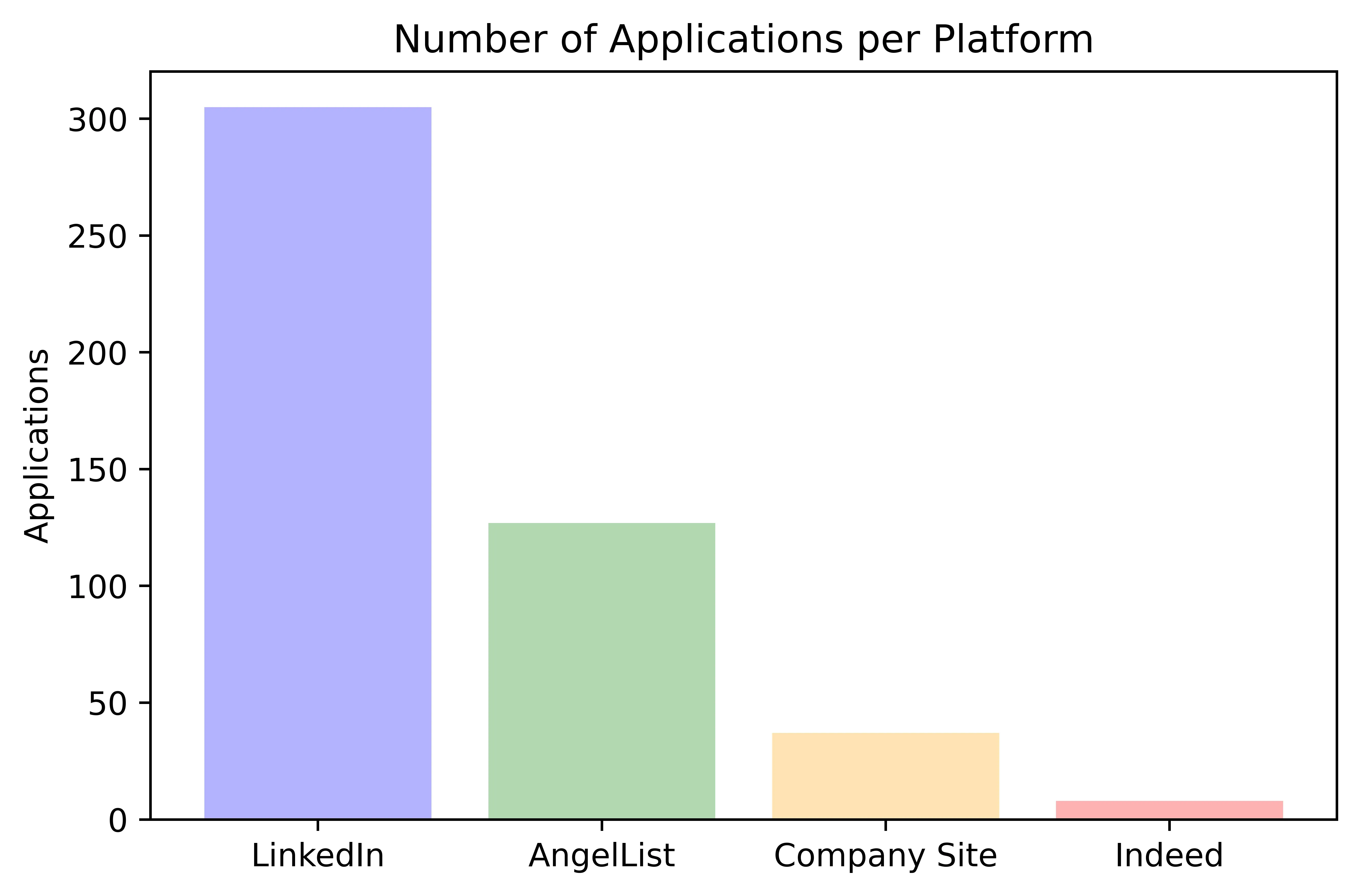
I Applied to 471 Jobs so You Only Have to Apply to 470
Sept. 4, 2022, 2:35 a.m.
0 Comments
No comments yet. Be the first to comment!
Leave a Comment